




The RS-25, also known as the Space Shuttle Main Engine (SSME), is a liquid-fuel cryogenic rocket engine that was used on NASA's Space Shuttle and is used on the Space Launch System.
Designed and manufactured in the United States by Rocketdyne (later Pratt & Whitney Rocketdyne and Aerojet Rocketdyne), the RS-25 burns cryogenic (very low temperature) liquid hydrogen and liquid oxygen propellants, with each engine producing 1,859 kN (418,000 lbf) thrust at liftoff. Although RS-25 heritage traces back to the 1960s, its concerted development began in the 1970s with the first flight, STS-1, on April 12, 1981. The RS-25 has undergone upgrades over its operational history to improve the engine's thrust, reliability, safety, and maintenance load.
The engine produces a specific impulse (Isp) of 452 seconds (4.43 kN⋅s/kg) in vacuum, or 366 seconds (3.59 kN⋅s/kg) at sea level, has a mass of approximately 3.5 tonnes (7,700 pounds), and is capable of throttling between 67% and 109% of its rated power level in one-percent increments. Components of the RS-25 operate at temperatures ranging from −253 to 3,300 °C (−400 to 6,000 °F).
The Space Shuttle used a cluster of three RS-25 engines mounted at the stern of the orbiter, with fuel drawn from the external tank. The engines were used for propulsion throughout the spacecraft ascent, with total thrust increased by two solid rocket boosters and the orbiter's two AJ10 orbital maneuvering system engines. Following each flight, the RS-25 engines were removed from the orbiter, inspected, refurbished, and then reused on another mission.
Four RS-25 engines are installed on each Space Launch System, housed in the engine section at the base of the core stage, and expended after use. The first four Space Launch System flights use modernized and refurbished engines built for the Space Shuttle program. Subsequent flights will make use of a simplified RS-25E engine called the Production Restart, which is under testing and development.
Contents
Components
The RS-25 engine consists of pumps, valves, and other components working in concert to produce thrust. Fuel (liquid hydrogen) and oxidizer (liquid oxygen) from the Space Shuttle's external tank entered the orbiter at the umbilical disconnect valves and from there flowed through the orbiter's main propulsion system (MPS) feed lines; whereas in the Space Launch System (SLS), fuel and oxidizer from the rocket's core stage flow directly into the MPS lines. Once in the MPS lines, the fuel and oxidizer each branch out into separate paths to each engine (three on the Space Shuttle, four on the SLS). In each branch, pre-valves then allow the propellants to enter the engine.
Once in the engine, the propellants flow through low-pressure fuel and oxidizer turbopumps (LPFTP and LPOTP), and from there into high-pressure turbopumps (HPFTP and HPOTP). From these HPTPs the propellants take different routes through the engine. The oxidizer is split into four separate paths: to the oxidizer heat exchanger, which then splits into the oxidizer tank pressurization and pogo suppression systems; to the low-pressure oxidizer turbopump (LPOTP); to the high-pressure oxidizer pre-burner, from which it is split into the HPFTP turbine and HPOTP before being reunited in the hot gas manifold and sent on to the main combustion chamber (MCC); or directly into the main combustion chamber (MCC) injectors.
Meanwhile, fuel flows through the main fuel valve into regenerative cooling systems for the nozzle and MCC, or through the chamber coolant valve. The fuel passing through the MCC cooling system then passes back through the LPFTP turbine before being routed either to the fuel tank pressurization system or to the hot gas manifold cooling system (from where it passes into the MCC). Fuel in the nozzle cooling and chamber coolant valve systems is then sent via pre-burners into the HPFTP turbine and HPOTP before being reunited again in the hot gas manifold, from where it passes into the MCC injectors. Once in the injectors, the propellants are mixed and injected into the main combustion chamber where they are ignited. The ejection of the burning propellant mixture through the throat and bell of the engine's nozzle creates the thrust.
Turbopumps
The low-pressure oxidizer turbopump (LPOTP) is an axial-flow pump which operates at approximately 5,150 rpm driven by a six-stage turbine powered by high-pressure liquid oxygen from the high-pressure oxidizer turbopump (HPOTP). It boosts the liquid oxygen's pressure from 0.7 to 2.9 MPa (100 to 420 psi), with the flow from the LPOTP then being supplied to the HPOTP. During engine operation, the pressure boost permits the high-pressure oxidizer pump to operate at high speeds without cavitating. The LPOTP, which measures approximately 450 by 450 mm (18 by 18 in), is connected to the vehicle propellant ducting and supported in a fixed position by being mounted on the launch vehicle's structure.
Then, mounted before the HPOTP, is the pogo oscillation suppression system accumulator. For use, it is pre-and post-charged with He and charged with gaseous O2 from the heat exchanger, and, not having any membrane, it operates by continuously recirculating the charge gas. A number of baffles of various types are present inside the accumulator to control sloshing and turbulence, which is useful of itself and also to prevent the escape of gas into the low-pressure oxidizer duct to be ingested in the HPOTP.
The HPOTP consists of two single-stage centrifugal pumps (the main pump and a pre-burner pump) mounted on a common shaft and driven by a two-stage, hot-gas turbine. The main pump boosts the liquid oxygen's pressure from 2.9 to 30 MPa (420 to 4,350 psi) while operating at approximately 28,120 rpm, giving a power output of 23,260 hp (17.34 MW). The HPOTP discharge flow splits into several paths, one of which drives the LPOTP turbine. Another path is to, and through, the main oxidizer valve and enters the main combustion chamber. Another small flow path is tapped off and sent to the oxidizer heat exchanger. The liquid oxygen flows through an anti-flood valve that prevents it from entering the heat exchanger until sufficient heat is present for the heat exchanger to utilize the heat contained in the gases discharged from the HPOTP turbine, converting the liquid oxygen to gas. The gas is sent to a manifold and then routed to pressurize the liquid oxygen tank. Another path enters the HPOTP second-stage pre-burner pump to boost the liquid oxygen's pressure from 30 to 51 MPa (4,300 psia to 7,400 psia). It passes through the oxidizer pre-burner oxidizer valve into the oxidizer pre-burner and through the fuel pre-burner oxidizer valve into the fuel pre-burner. The HPOTP measures approximately 600 by 900 mm (24 by 35 in). It is attached by flanges to the hot-gas manifold.
The HPOTP turbine and HPOTP pumps are mounted on a common shaft. Mixing of the fuel-rich hot gases in the turbine section and the liquid oxygen in the main pump can create a hazard and, to prevent this, the two sections are separated by a cavity that is continuously purged by the engine's helium supply during engine operation. Two seals minimize leakage into the cavity; one seal is located between the turbine section and the cavity, while the other is between the pump section and cavity. Loss of helium pressure in this cavity results in automatic engine shutdown.
Powerhead
The oxidizer and fuel pre-burners are welded to the hot-gas manifold. The fuel and oxidizer enter the pre-burners and are mixed so that efficient combustion can occur. The augmented spark igniter is a small combination chamber located in the center of the injector of each pre-burner. Two dual-redundant spark igniters are activated by the engine controller and are used during the engine start sequence to initiate combustion in each pre-burner. They are turned off after approximately three seconds because the combustion process is then self-sustaining. The pre-burners produce the fuel-rich hot gases that pass through the turbines to generate the power needed to operate the high-pressure turbopumps. The oxidizer pre-burner's outflow drives a turbine that is connected to the HPOTP and to the oxidizer pre-burner pump. The fuel pre-burner's outflow drives a turbine that is connected to the HPFTP.
The speed of the HPOTP and HPFTP turbines depends on the position of the corresponding oxidizer and fuel pre-burner oxidizer valves. These valves are positioned by the engine controller, which uses them to throttle the flow of liquid oxygen to the pre-burners and, thus, control engine thrust. The oxidizer and fuel pre-burner oxidizer valves increase or decrease the liquid oxygen flow, thus increasing or decreasing pre-burner chamber pressure, HPOTP and HPFTP turbine speed, and liquid oxygen and gaseous hydrogen flow into the main combustion chamber, which increases or decreases engine thrust. The oxidizer and fuel pre-burner valves operate together to throttle the engine and maintain a constant 6.03:1 propellant mixture ratio.
The main oxidizer and main fuel valves control the flow of liquid oxygen and liquid hydrogen into the engine and are controlled by each engine controller. When an engine is operating, the main valves are fully open.
The engine's main combustion chamber (MCC) receives fuel-rich hot gas from a hot-gas manifold cooling circuit. The gaseous hydrogen and liquid oxygen enter the chamber at the injector, which mixes the propellants. The mixture is ignited by the "Augmented Spark Igniter", an H2/O2 flame at the center of the injector head. The main injector and dome assembly are welded to the hot-gas manifold, and the MCC is also bolted to the hot-gas manifold. The MCC comprises a structural shell made of Inconel 718 which is lined with a copper-silver-zirconium alloy called NARloy-Z, developed specifically for the RS-25 in the 1970s. Around 390 channels are machined into the liner wall to carry liquid hydrogen through the liner to provide MCC cooling, as the temperature in the combustion chamber reaches 3,300 °C (5,970 °F) during flight – higher than the boiling point of iron.
Nozzle
The engine's nozzle is 121 in (3.1 m) long with a diameter of 10.3 inches (0.26 m) at its throat and 90.7 inches (2.30 m) at its exit. The nozzle is a bell-shaped extension bolted to the main combustion chamber, referred to as a de Laval nozzle. The RS-25 nozzle has an unusually large expansion ratio (about 69:1) for the chamber pressure. At sea level, a nozzle of this ratio would normally undergo flow separation of the jet from the nozzle, which would cause control difficulties and could even mechanically damage the vehicle. However, to aid the engine's operation Rocketdyne engineers varied the angle of the nozzle walls from the theoretical optimum for thrust, reducing it near the exit. This raises the pressure just around the rim to an absolute pressure between 4.6 and 5.7 psi (32 and 39 kPa), and prevents flow separation. The inner part of the flow is at much lower pressure, around 2 psi (14 kPa) or less. The inner surface of each nozzle is cooled by liquid hydrogen flowing through brazed stainless steel tube wall coolant passages. On the Space Shuttle, a support ring welded to the forward end of the nozzle is the engine attach point to the orbiter-supplied heat shield. Thermal protection is necessary because of the exposure portions of the nozzles experience during the launch, ascent, on-orbit and entry phases of a mission. The insulation consists of four layers of metallic batting covered with a metallic foil and screening.
Controller
Each engine is equipped with a main engine controller (MEC), an integrated computer which controls all of the engine's functions (through the use of valves) and monitors its performance. Built by Honeywell Aerospace, each MEC originally comprised two redundant Honeywell HDC-601 computers, later upgraded to a system composed of two doubly redundant Motorola 68000 (M68000) processors (for a total of four M68000s per controller). Having the controller installed on the engine itself greatly simplifies the wiring between the engine and the launch vehicle, because all the sensors and actuators are connected directly to only the controller, each MEC then being connected to the orbiter's general purpose computers (GPCs) or the SLS's avionics suite via its own engine interface unit (EIU). Using a dedicated system also simplifies the software and thus improves its reliability.
Two independent dual-CPU computers, A and B, form the controller; giving redundancy to the system. The failure of controller system A automatically leads to a switch-over to controller system B without impeding operational capabilities; the subsequent failure of controller system B would provide a graceful shutdown of the engine. Within each system (A and B), the two M68000s operate in lock-step, thereby enabling each system to detect failures by comparing the signal levels on the buses of the two M68000 processors within that system. If differences are encountered between the two buses, then an interrupt is generated and control turned over to the other system. Because of subtle differences between M68000s from Motorola and the second source manufacturer TRW, each system uses M68000s from the same manufacturer (for instance system A would have two Motorola CPUs while system B would have two CPUs manufactured by TRW). Memory for block I controllers was of the plated-wire type, which functions in a manner similar to magnetic core memory and retains data even after power is turned off. Block II controllers used conventional CMOS static RAM.
The controllers were designed to be tough enough to survive the forces of launch and proved to be extremely resilient to damage. During the investigation of the Challenger accident the two MECs (from engines 2020 and 2021), recovered from the seafloor, were delivered to Honeywell Aerospace for examination and analysis. One controller was broken open on one side, and both were severely corroded and damaged by marine life. Both units were disassembled and the memory units flushed with deionized water. After they were dried and vacuum baked, data from these units was retrieved for forensic examination.
Gimbal
Each engine is installed with a gimbal bearing, a universal ball and socket joint which is bolted to the launch vehicle by its upper flange and to the engine by its lower flange. It represents the thrust interface between the engine and the launch vehicle, supporting 7,480 lb (3,390 kg) of engine weight and withstanding over 500,000 lbf (2,200,000 N) of thrust. As well as providing a means to attach the engine to the launch vehicle, the gimbal bearing allows the engine to be pivoted (or "gimballed") around two axes of freedom with a range of ±10.5°. This motion allows the engine's thrust vector to be altered, thus steering the vehicle into the correct orientation. The comparatively large gimbal range is necessary to correct for the pitch momentum that occurs due to the constantly shifting center of mass as the vehicle burns fuel in flight and after booster separation. The bearing assembly is approximately 290 by 360 mm (11 by 14 in), has a mass of 105 lb (48 kg), and is made of titanium alloy.
The low-pressure oxygen and low-pressure fuel turbopumps were mounted 180° apart on the orbiter's aft fuselage thrust structure. The lines from the low-pressure turbopumps to the high-pressure turbopumps contain flexible bellows that enable the low-pressure turbopumps to remain stationary while the rest of the engine is gimbaled for thrust vector control, and also to prevent damage to the pumps when loads were applied to them. The liquid-hydrogen line from the LPFTP to the HPFTP is insulated to prevent the formation of liquid air.
Helium system
In addition to fuel and oxidizer systems, the launch vehicle's main propulsion system is also equipped with a helium system consisting of ten storage tanks in addition to various regulators, check valves, distribution lines, and control valves. The system is used in-flight to purge the engine and provides pressure for actuating engine valves within the propellant management system and during emergency shutdowns. During entry, on the Space Shuttle, any remaining helium was used to purge the engines during reentry and for repressurization.
History
Development
The history of the RS-25 traces back to the 1960s when NASA's Marshall Space Flight Center and Rocketdyne were conducting a series of studies on high-pressure engines, developed from the successful J-2 engine used on the S-II and S-IVB upper stages of the Saturn V rocket during the Apollo program. The studies were conducted under a program to upgrade the Saturn V engines, which produced a design for a 350,000 lbf (1,600 kN) upper-stage engine known as the HG-3. As funding levels for Apollo wound down the HG-3 was cancelled as well as the upgraded F-1 engines already being tested. It was the design for the HG-3 that would form the basis for the RS-25.
Meanwhile, in 1967, the US Air Force funded a study into advanced rocket propulsion systems for use during Project Isinglass, with Rocketdyne asked to investigate aerospike engines and Pratt & Whitney (P&W) to research more efficient conventional de Laval nozzle-type engines. At the conclusion of the study, P&W put forward a proposal for a 250,000 lbf engine called the XLR-129, which used a two-position expanding nozzle to provide increased efficiency over a wide range of altitudes.
In January 1969 NASA awarded contracts to General Dynamics, Lockheed, McDonnell Douglas, and North American Rockwell to initiate the early development of the Space Shuttle. As part of these 'Phase A' studies, the involved companies selected an upgraded version of the XLR-129, developing 415,000 lbf (1,850 kN), as the baseline engine for their designs. This design can be found on many of the planned Shuttle versions right up to the final decision. However, since NASA was interested in pushing the state of the art in every way they decided to select a much more advanced design in order to "force an advancement of rocket engine technology". They called for a new design based on a high-pressure combustion chamber running around 3,000 psi (21,000 kPa), which increases the performance of the engine.
Development began in 1970, when NASA released a request for proposal for 'Phase B' main engine concept studies, requiring development of a throttleable, staged combustion, de Laval-type engine. The request was based on the then-current design of the Space Shuttle which featured two reusable stages, the orbiter and a crewed fly-back booster, and required one engine which would be able to power both vehicles via two different nozzles (12 booster engines with 550,000 lbf (2,400 kN) sea level thrust each and 3 orbiter engines with 632,000 lbf (2,810 kN) vacuum thrust each). Rocketdyne, P&W and Aerojet General were selected to receive funding although, given P&W's already-advanced development (demonstrating a working 350,000 lbf (1,600 kN) concept engine during the year) and Aerojet General's prior experience in developing the 1,500,000 lbf (6,700 kN) M-1 engine, Rocketdyne was forced to put a large amount of private money into the design process to allow the company to catch up to its competitors.
Space Shuttle program
Each Space Shuttle had three RS-25 engines, installed in the aft structure of the Space Shuttle orbiter in the Orbiter Processing Facility prior to the orbiter being transferred to the Vehicle Assembly Building. If necessary, the engines could be changed on the pad. The engines, drawing propellant from the Space Shuttle external tank (ET) via the orbiter's main propulsion system (MPS), were ignited at T−6.6 seconds prior to liftoff (with each ignition staggered by 120 ms), which allowed their performance to be checked prior to ignition of the Space Shuttle Solid Rocket Boosters (SRBs), which committed the shuttle to the launch. At launch, the engines would be operating at 100% RPL, throttling up to 104.5% immediately following liftoff. The engines would maintain this power level until around T+40 seconds, where they would be throttled back to around 70% to reduce aerodynamic loads on the shuttle stack as it passed through the region of maximum dynamic pressure, or max. q. The engines would then be throttled back up until around T+8 minutes, at which point they would be gradually throttled back down to 67% to prevent the stack exceeding 3 g of acceleration as it became progressively lighter due to propellant consumption. The engines were then shut down, a procedure known as main engine cutoff (MECO), at around T+8.5 minutes.
After each flight the engines would be removed from the orbiter and transferred to the Space Shuttle Main Engine Processing Facility (SSMEPF), where they would be inspected and refurbished in preparation for reuse on a subsequent shuttle flight. A total of 46 reusable RS-25 engines, each costing around US$40 million, were flown during the Space Shuttle program, with each new or overhauled engine entering the flight inventory requiring flight qualification on one of the test stands at the Stennis Space Center prior to flight.
Over the course of the Space Shuttle program, the RS-25 went through a series of upgrades, including combustion chamber changes, improved welds and turbopump changes in an effort to improve the engine's performance and reliability and so reduce the amount of maintenance required after use. As a result, several versions of the RS-25 were used during the program:
FMOF (first manned orbital flight): Certified for 100% rated power level (RPL). Used for the orbital flight test missions STS-1 – STS-5 (engines 2005, 2006 and 2007).
Phase I: Used for missions STS-6 – STS-51-L, the Phase I engine offered increased service life and was certified for 104% RPL. Replaced by Phase II after the Challenger Disaster.
Constellation program
During the period preceding final Space Shuttle retirement, various plans for the remaining engines were proposed, ranging from them all being kept by NASA, to them all being given away (or sold for US$400,000–800,000 each) to various institutions such as museums and universities. This policy followed changes to the planned configurations of the Constellation program's Ares V cargo-launch vehicle and Ares I crew-launch vehicle rockets, which had been planned to use the RS-25 in their first and second stages respectively. While these configurations had initially seemed worthwhile, as they would use then-current technology following the shuttle's retirement in 2010, the plan had several drawbacks:
The engines would not be reusable, as they would be permanently attached to the discarded stages and disposed of in the atmosphere.
Each engine would have to undergo a test firing prior to installation and launch, with refurbishment required following the test.
It would be expensive, time-consuming, and weight-intensive to convert the ground-started RS-25D to an air-started version for the Ares I second stage.
Following several design changes to the Ares I and Ares V rockets, the RS-25 was replaced with a single J-2X engine for the Ares I second stage and six modified RS-68 engines (which was based on both the SSME and Apollo-era J-2 engine) on the Ares V core stage; these changes meant that the RS-25 would be retired along with the Shuttle fleet. In 2010, however, NASA was directed to halt the Constellation program, and with it development of the Ares I and Ares V, instead of focusing on building a new heavy-lift launcher.
XS-1
On May 24, 2017, DARPA announced that they had selected The Boeing Company to complete design work on the XS-1 program. The technology demonstrator was planned to use an Aerojet Rocketdyne AR-22 engine. The AR-22 was a version of the RS-25, with parts sourced from Aerojet Rocketdyne and NASA inventories from early versions of the engine. In July 2018 Aerojet Rocketdyne successfully completed ten 100-second firings of the AR-22 in ten days.
On January 22, 2020, Boeing announced its departure from the XS-1 program, leaving no role for the AR-22.
Present use
Space Launch System
On 14 September 2011, following the retirement of the Space Shuttle, NASA announced that it would be developing a new launch vehicle, known as the Space Launch System (SLS), to replace the shuttle fleet. The design for the SLS features the RS-25 as part of its core stage, with different versions of the rocket being equipped with between three and five engines. The initial flights of the new launch vehicle are making use of previously flown Block II RS-25D engines, with NASA keeping such engines in a "purged safe" environment at Stennis Space Center, "along with all of the ground systems required to maintain them." For Artemis I, the RS-25D units with serial numbers E2045, E2056, E2058, and E2060 from all three orbiters were used. They were installed on the core stage by November 6, 2019. For Artemis II, the units with serial numbers E2047, E2059, E2062, and E2063 were slated to be used. They were installed on the core stage by September 25, 2023. In spring 2025, engine E2063 was replaced with E2061 after a leak was discovered in its oxygen valve hydraulics.
In addition to the RS-25Ds, the SLS program makes use of the Main Propulsion Systems (MPS, the "plumbing" feeding the engines) from the three remaining shuttle orbiters for testing purposes (having been removed as part of the orbiters' decommissioning), with the first two launches (Artemis I and Artemis II) originally predicted to make use of the MPS hardware from Space Shuttles Atlantis and Endeavour in their core stages. The SLS's propellants are supplied to the engines from the rocket's core stage, which consists of a modified Space Shuttle external tank with the MPS plumbing and engines at its aft, and an interstage structure at the top.
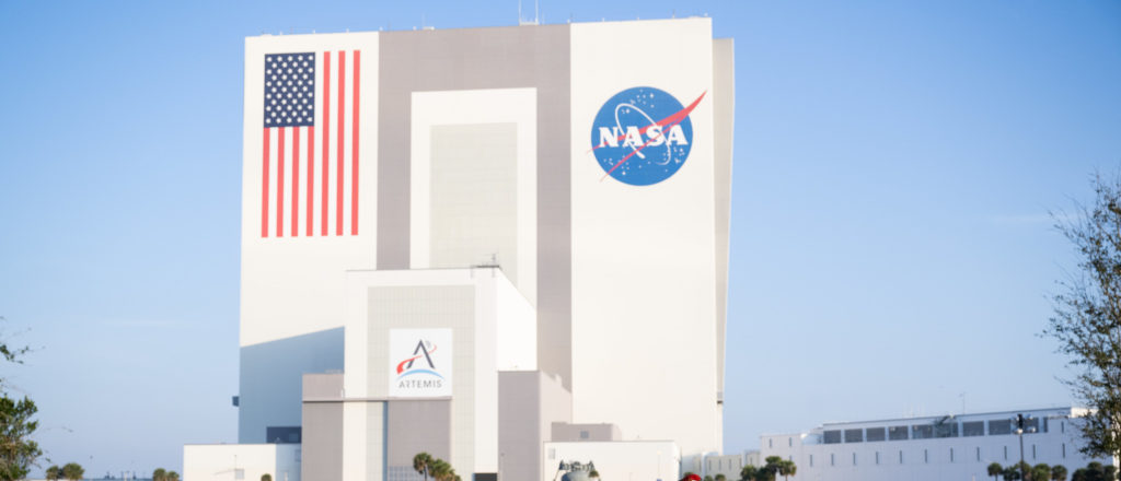
For the first two Artemis missions, the engines were installed on the SLS core stage in Building 103 of the Michoud Assembly Facility; they will be installed in the Space Station Processing Facility at Kennedy beginning with Artemis III.
Once the remaining RS-25Ds are exhausted, they are to be replaced with a cheaper, expendable version designated the RS-25E. In 2023, Aerojet Rocketdyne reported reductions in manufacturing time and labor requirements during manufacturing of new-production RS-25 engines, such as a 15% reduction in fabrication time for the powerhead and a 22-month reduction in the time needed to produce a main combustion chamber.
On 1 May 2020, NASA awarded a contract extension to manufacture 18 additional RS-25 engines, with associated services, for $1.79 billion, bringing the total SLS contract value to almost $3.5 billion.